LSG-1890BCCD/LSG-1800ACCD goniospectroradiometer is high precision automatic goniophotometric instrument for luminous intensity distribution measurement with facility for rotating the light source. The LSG-1890BCCD/LSG-1800ACCD can do the spatial CCT test and the intensity distribution test. It is for industrial laboratory photometric data measurement of luminaires such as LED luminaires, LED Plant Lighting, HID luminaires, fluorescent lamps and so on.
Measurement:
Luminous Intensity Data, Luminous Intensity Distribution, Zonal Luminous Flux, Luminaries Efficiency, Luminance Distribution(Option), Coefficient Of Utilization, Luminance Limitation Curves Glare, Maximum Ratio of Distance to Height, Equal Illuminance Diagrams, Curves of Luminaires VS Lighting Area, Isocandela Diagrams, Efficient Luminescence Angle, EEI, UGR, CCT, CRI, Color Temperature Distribution, Spectrum, (x, y)/(u, v), PAR, PPF, PPFD 3D distribution test and etc.
Q1:The software cannot communicate with the device.
A1:① Confirm that the driver of the communication box is successfully installed.
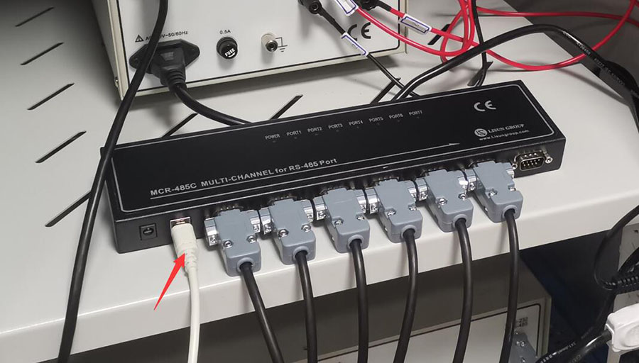
 ② Connect the other end of the USB cable of the communication box to a USB port with stable power supply on the computer, and try not to use USB extension cables. The communication box is powered via USB cable.

③System configuration interface. Refer to the user manual and all the devices of the system you purchased, select the correct models for all devices, and then click “Auto Search Communication Port”.

If there is still an error message, please check whether the corresponding device has been purchased, whether the model is selected correctly, and whether the communication cable is connected correctly according to the prompt content.
Q2:A parameter on the front panel of digital power meter shows a negative value.
A2:Please check the wiring on the back of the power meter and confirm that the four wires A1 A2 V1 V2 are connected to the correct terminals.

Q3:The electrical parameters displayed on the digital power meter and the power supply are inconsistent.
A3:①The voltage displayed on the power supply is the total voltage of the entire circuit, while the digital power meter uses the four-wire measurement method, and the voltage displayed is the voltage value at the sample after removing the line voltage drop.
② Error caused by accuracy. The accuracy of DC power supply is higher than that of LS series digital power meter. The accuracy of LS series digital power meter is higher than that of AC power supply.
Q4:When the software opens, it prompts “File is not a database”.
A4:Click the white button in the picture below to create a new database file and save it on your computer. Subsequent test results will be automatically saved in this file. If this file is deleted or moved, you need to reopen the database file or create a new database file. If the computer is not logged in with an administrator account, the database file or the contents in the file may be automatically deleted. Please try to log in your computer with an administrator account.

Q5:The standard lamp can’t be turned on automatically.
A5:① Confirm that the AC/DC switch is at DC.

②Confirm that the input voltage and current are consistent with the standard lamp certificate, and be sure to select CC (constant current mode):

③Check whether the filament of the standard lamp is still intact. Severe impact during transportation and handling may cause the filament to break:

④Check the connection of the four banana-plug cables from the cabinet to the goniophotometer, and check the connection of the standard lamp power cable.
Q6:The difference between the calibration distance and the actual distance is big.
A6:After the calibration is successful, the calibration distance automatically calculated by the software is displayed here:

The actual distance is the distance from the center of the goniophotometer to the photo detector. You can refer to the darkroom drawings or actually measure it.
The difference between the two distances should be within 2% or less. If the difference is too large, the following steps may not be done well enough:
a. The standard lamp is unstable. The standard lamp needs about 15 minutes to be stable after turned on. Calibration can be performed when it is stable.
b. The darkroom is not painted completely matte black. There may be light leakage or reflection.
c. The hardware adjustment is not adjusted properly. Including the goniophotometer level, photo detector position and direction, Gamma axis zero direction, etc.
d. During calibration, the direction of the standard lamp is incorrectly adjusted.
Please check the darkroom and refer to the user manual to make sure every step is done correctly.
Q7:Under what circumstances is recalibration required?
A7:① If there are no changes in the darkroom or computer, theoretically there is no need to calibrate again.
② If you change the computer, you do not need to do the candela calibration again. You can directly enter the previous test distance and save it. However, spectrum calibration needs to be re-operated.
③ If the darkroom is replaced, both the candela calibration and spectrum calibration need to be re-operated.
Q8:Software can’t get electrical parameters.
A8:Please confirm that you selected the correct power meter model and the correct COM port. See the figure below:

If your power meter is only for AC, so please select DC power supply as the DC power meter if your sample is DC lamp. See the figure below:

Q9:DC samples can’t be turned on automatically.
A9:Please confirm that the voltage and current of the sample is within the limit of the DC power supply. For example, the limit voltage is 30V and the limit current is 10A for DC3010 DC power supply.
If the sample needs constant current (CC), you need to input its rated current and a high enough voltage.
If the sample needs constant voltage (CV), you need to input its rated voltage and a high enough current.

Q10:The test result is 0
A10:① Please check whether the calibration distance is normal. If the computer is not logged in with an administrator account or for other reasons, the calibration distance may be tampered with by the computer to 0. Please change it to the correct test distance:

② Check the K factor at “System Configuration” of the goniophotometer software (No need to check if with no “K factor” option). Under normal circumstances without an attenuator, the K factor is 1. If you purchased an attenuator, please consult us to get the K factor of the attenuator. If the K factor is written as 0, the test result will be 0.
Q11:How to test a double-sided light?
A11:Some lamps emit light from both upper and lower sides, see the picture below:

First, it needs to be tested twice. That is, once for the upward-emitting part and once for the downward-emitting part. Then hold down the “Control” key on the keyboard, select two test reports at the same time, and click “Combine” on the navigation bar to combine the two reports into one. See below:

The combined file is the test report of the entire luminaire, as shown below:

Q12:The total luminous flux test is incorrect.
A12:①Confirm that the difference between the calibration distance and the actual distance is within the normal range (Refer to item 6 above).
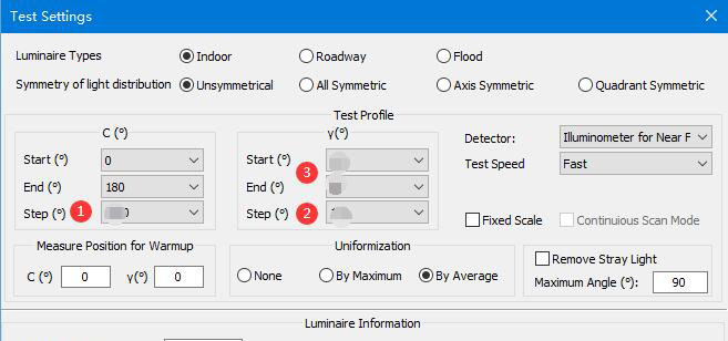
②If the sample is an asymmetric lamp, such as a street lamp, ①C (B) angle interval should be set smaller, such as 5 degrees or 10 degrees. If the sample is a symmetrical lamp, such as an indoor lamp, the C (B) angle interval can be set a little bigger, such as 22.5 degrees or 30 degrees. If there are no special requirements, the angle interval of ②Gamma (Beta) shall be 1 degree in any case.
During the C-Gamma test, if the illumination angle of the sample lamp is greater than 180 degrees, the ③ Gamma test angle range needs to be set to -180 to 180 degrees.

③Make sure the temperature in the darkroom is below 35 degrees.
④When testing, please confirm that the sample lamp is already stable, and all other lighting in the darkroom is turned off.
Q13:The shape of the light intensity distribution curve is abnormal.
A13:①Please confirm that the luminous surface of the luminaire is parallel to the cross clamp, and use the cross laser to ensure that the luminous surface is in the center of the cross clamp. If the installation direction of the lamp is not correct, it will definitely lead to abnormal light intensity distribution curve.
②If the luminaire is an asymmetric lamp, the sample may have different light intensity distribution curves at different C angles (the rotation angle of the red arrow in the figure below), which is normal.

Q14:The CU curve of road lamp is abnormal.
A14:Street lights are directional. If they are installed in the wrong direction, some test parameters such as the CU curve may be abnormal. The correct installation direction is as shown in the figure below. In the C0 direction, the street light pole should be facing directly upward (if your goniophotometer is LSG-6000 mirror type, it should be facing the direction of the goniophotometer).

Q15:Color test (Color distribution test) cannot be performed.
A15:The software will automatically determine how to perform the color test based on the light intensity distribution curve. If the light intensity distribution test is not performed first, the color test will be unavailable, as shown in the figure below:

When performed a light intensity distribution test and opening the corresponding light intensity distribution test report, the color test is available, as shown in the figure below:

Q16:The luminous flux of the exported IES file is displayed as -1.
A16:See the figure below:

What is displayed here in the IES file is the light source luminous flux. If the light source luminous flux is not filled in, -1 will be displayed here according to the 2019 version of the standard. Fill in the “Number of Lamps” and the “Lumens per Lamp”:

Then re-export the IES file, you can see the displayed light source luminous flux:

Q17:The exported LDT file light intensity data is inconsistent with the goniophotometer test report data.
A17:The unit used in the LDT file is cd/klm, as shown in the figure below:

Our goniophotometer can also modify the unit according to the standard. Using the same unit, the same light intensity data can be obtained. See below:

Q18:Half of the exported LDT file data is 0.
A18:See the figure below:

The LDT file is for indoor lamps. If you use the B-Beta reports to export the LDT file, the data will be abnormal. Please use the C-Gamma reports to export the LDT file.
Q19:How to maintain the goniophotometer?
A19:① Keep the darkroom as dust-free as possible. If there is a lot of dust, the photo detector surface needs to be cleaned regularly (be careful not to scratch the detector surface).
②The hardware part does not require maintenance. The internal lubricant can be used for about 10 years.
Q20:The UGR table in the test report cannot be displayed normally.
A20:See the figure below:

The software needs the size of the light-emitting surface of the luminaire to calculate the UGR data. Please enter the “Luminous length” and “Luminous width” correctly to get the correct UGR table, as shown in the figure below:

Q21:The test reports are defective when testing samples with very weak luminous intensity.
A21:The accuracy of the conventional detector of the goniophotometer is CLASS A, that is, the illumination value can be measured to a minimum of 0.001lx. But at the same time, the requirements for darkrooms and operating procedures and operators will be very high, so the situation is different in each laboratory.
The LSG-6000 series is equipped with a far-field detector and a near-field detector. Please try to use the far-field detector for testing. If the report is defective because the sample light intensity is too low, please switch to the near-field detector for testing.
LSG-1800A and LSG-1890B series are normally equipped with only one detector. If the report is defective because the light intensity of the sample is too low, it is recommended to add another detector for testing. In this way, the system will include a near-field photometric detector and a far-field photometric detector. If the light intensity of the sample is too low and the far-field detector reports defects, you can switch to the near-field detector for testing.
Q22:How does the software display illumination values from other distances?
A22:In the software, click on the “Lux-Distance” tab, as shown in the figure below. Click the gear button to open the setting interface, and you can set any distances and other related parameters required.

Note: Each tab has similar settings, please feel free to set them as needed.
Q23:The values displayed in the UGR table is incorrect.
A23:① First, please confirm that the size of the luminous surface filled in is correct. For the same test report, if the size of the luminous surface is different, the UGR table data will also be different.
② Please confirm that you have selected the same standard, as shown in the figure below. The calculation methods of different standards are also different. Currently, the latest standard is generally used, which is CIE 190:2010:

Q24:Which value in the UGR table is used to represent the UGR value of indoor lighting fixtures?
A24:UGR is a data table. If it is represented by only one value, according to the DLC SSL Technical Requirements Version 5.1, room dimension: X=4H, Y=8H, the reflectances 70/50/20%. Then you should choose the larger of the two values in the figure below as the UGR value:

Note: If you need to refer to other standard requirements, please refer to the corresponding standard content.
Q25:How to input the luminous dimensions for a round lamp?
A25:Input the diameter as a negative value for length and width, then you can get a round lamp:

Q26:How to open an IES or an IGF file (IGF file is generated by LISUN’s old goniophotometer software) with the latest version goniophotometer software?
A26:Click “+” and select the corret format:

Note: if you open a IES file which with incorrect file content format, the software will error.
Q27:Everything looks normal, but the software still can’t communicate with the AC power supply.
A27:Check the baudrate of it, and confirm it is 9600. If not, please set it to 9600.

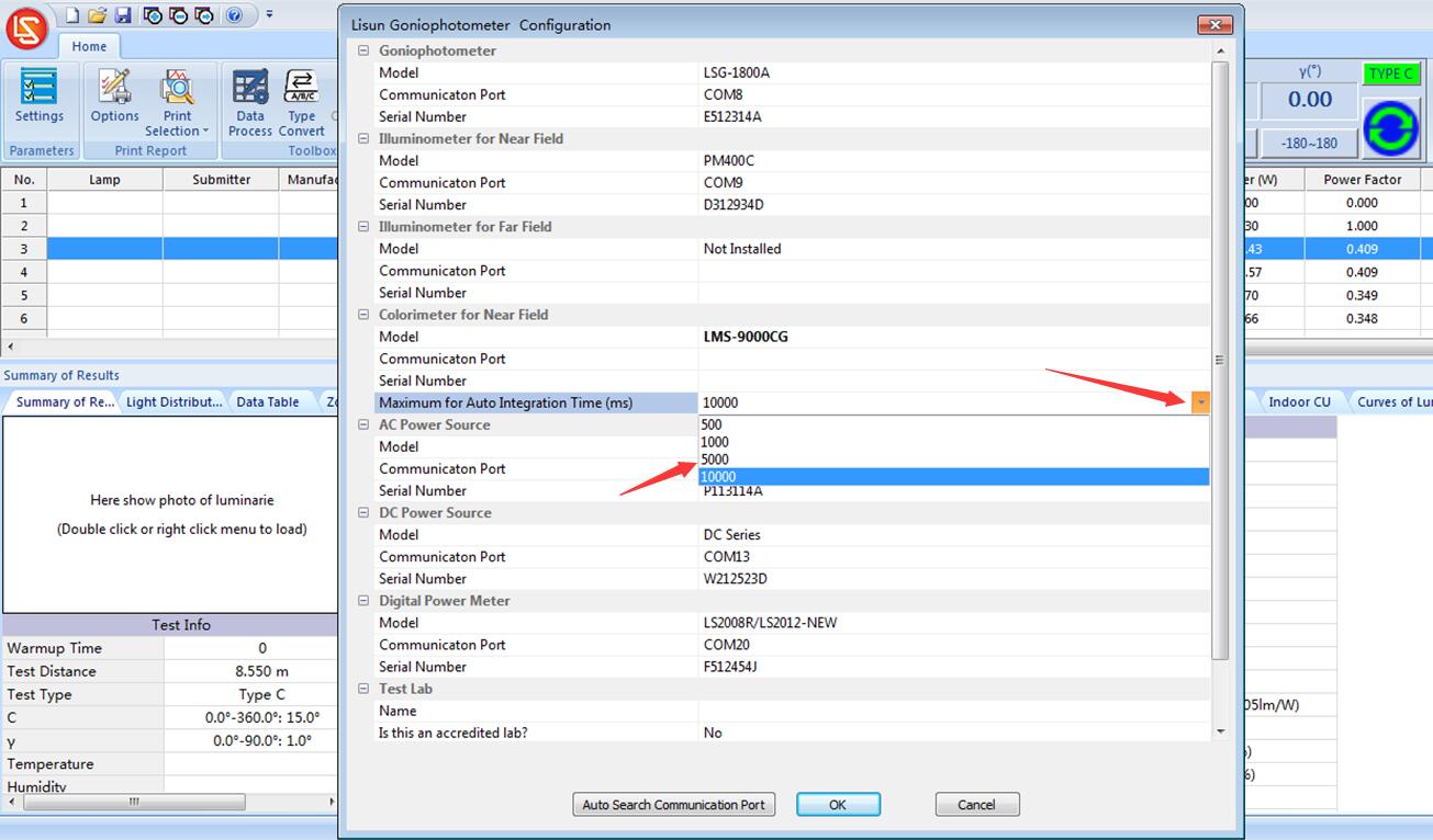
Q28:”Signal is too weak” when you test colorimetric parameters for lamp with weak light.
A28:Change the maximum intergration time longer and run a test again:

Q29:Software navigation is not fully displayed
A29:Due to the low resolution of the monitor, the navigation column may not be fully displayed. You can also force the navigation column to be displayed in full, as shown below. However, if the screen resolution is low, the navigation bar may be displayed abnormally after it is fully displayed. It is recommended to replace the monitor with a higher resolution.

Q30:How to use the attenuator for the detector?
A30:Old models of goniophotometers such as LSG-1600B, LSG-1700B, LSG-1800B, LSG-5000B, etc., if the photo detector exceeds the limit, requires a longer darkroom or the use of an attenuator. Please install the attenuator to the detector, and then fill in the correct K factor when testing. Each attenuator has a corresponding K factor. If two attenuators are used at the same time, the two K factors are multiplied to obtain a new K factor:

Q31:Why “UGR table not available” when you open IES or LDT file with LDT editor?
See the figure below:

UGR table not available
A31:According to the LDT standard, the lamps must be fully symmetrical in order to automatically calculate the UGR table. When testing indoor lamps, please select “fully symmetrical” as shown in the figure below, and then the UGR table can be calculated normally when the LDT standard is applied:

Test indoor lamp with “All symmetric”
Products that have been tested do not need to be tested again. Open the corresponding test report in the software, click “Type Converter” to change all the start and end angles of the C axis to 0 degrees, and keep other parameters unchanged, and re-generate a symmetrical test report. See the figure below:

Change Goniophotometer Test Report To Symmetric
Q32:How to install LED tube lamp correctly?
A32:When both axes of the goniophotometer C-Gamma are at 0 degrees, please install the LED tube lamp vertically, as shown in the figure below:

how to install the LED tube lamp on goniophotometer?
Q33:Too many test reports are saved in the same database file, which affects the running speed of the software.
A33:If you always open the same database file by default, after a long time, there will be too many test reports saved in the file, which will affect the software running speed and make it inconvenient to find a certain test report. It is recommended to create different database files for different samples to facilitate saving and searching. Note: Every time the software is opened, the last database file is opened by default. If the file has changed, the software will automatically pop up the dialog box for creating a new database file, and you can directly create a new database file.
Click the button in the figure below to create a new database file:

Build a new database file
Q34:How to confirm whether the candela calibration is accurate?
A34:The goniophotometer system uses a candela standard lamp, not a luminous flux standard lamp. According to the formula: candela = illuminance * distance 2, during calibration, the photo detector will monitor the real-time illuminance value. After entering its standard candela value, the software will automatically calculate the test distance according to the formula to complete the calibration. You can measure the actual distance, that is, the distance from the center of the goniophotometer to the surface of the detector. If it is very close to the calibration distance, there is no problem with the calibration. If the difference between the two is relatively large, please refer to Q6 of this FAQ to confirm where the problem is.
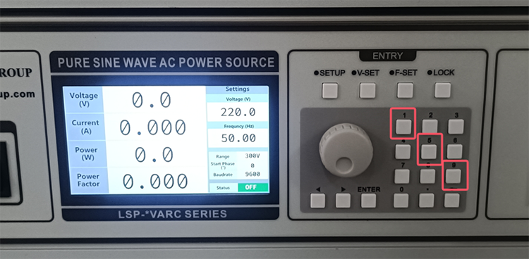
Q35:How to switch the interface display language of LSP series AC power supply?
A35:See the figure below. Press the number keys 1, 5, and 9 at the same time to switch the interface display language between Chinese and English:

Change the diplay language of LSP series power supply
Lisun Instruments Limited was found by LISUN GROUP in 2003. LISUN quality system has been strictly certified by ISO9001:2015. As a CIE Membership, LISUN products are designed based on CIE, IEC and other international or national standards. All products passed CE certificate and authenticated by the third party lab.
Our main products are Goniophotometer, Integrating Sphere, Spectroradiometer, Surge Generator, ESD Simulator Guns, EMI Receiver, EMC Test Equipment, Electrical Safety Tester, Environmental Chamber, Temperature Chamber, Climate Chamber, Thermal Chamber, Salt Spray Test, Dust Test Chamber, Waterproof Test, RoHS Test (EDXRF), Glow Wire Test and Needle Flame Test.
Please feel free to contact us if you need any support.
Tech Dep: Service@Lisungroup.com, Cell/WhatsApp:+8615317907381
Sales Dep: Sales@Lisungroup.com, Cell/WhatsApp:+8618117273997
Your email address will not be published. Required fields are marked *