LPCE-3 is a CCD Spectroradiometer Integrating Sphere Compact System for LED Testing. It is suitable for single LED and LED luminaires’ photometric, colorimetric and electrical measurement. The measured data meets the requirements of CIE 177, CIE84, CIE-13.3, COMMISSION DELEGATED REGULATION (EU) 2019/2015, IES LM-79-19, Optical-Engineering-49-3-033602, IESNA LM-63-2, ANSI-C78.377 and GB standards
The Sphere System Configuration:
CCD Spectroradiometer (LMS-7000), Optical Fiber (CFO-1.5M), Digital Power Meter (LS2008R), DC Power Source (DC-S Series), AC Power Source (LSP-500VAS), Integrating Sphere (IS-1.5MA-CASE and IS-0.3M), Standard Light Source (SLS-50W and SLS-10W)
Measurement:
• Colorimetric: Chromaticity coordinates, CCT, Color Ratio, Peak Wavelength, Half Bandwidth, Dominant Wavelength, Color Purity, CRI (Ra, R1 to R15), Spectrum Test, TM30 (Rf, Rg), CQS
• Photometric: Luminous Flux, Luminous Efficiency, Radiant Power, EEI, PAR, PPF
• Electrical: Voltage, Current, Power, Power Factor, Harmonic (Optional)

Specification:
• Spectral Range Wavelength: 350nm~950nm(LMS-7000VIS) (200~1050nm is optional)
• Spectral Wavelength Accuracy: ±0.5nm Wavelength Reproducibility: ±0.5nm
• Sample Scanning Steps: ±0.1nm
• Accuracy of Chromaticity Coordinate (Δx, Δy): ±0.003 (under Standard A Lamp)
• Correlated Color Temperature CCT: 1,500K~25,000K. CCT Accuracy: ±0.5%
• Color Rendering Index Range: 0~100.0, Accuracy: ± (0.3%rd±0.3)
• Photometric linear: ±0.5%
• Stray light: <0.015% (600nm) and <0.03% (435nm)
• The system includes the auxiliary lamp device and the software includes self-absorption function
• Connect with PC via USB cable. The English version software can run in Win7, Win8, Win10, Win11 (The driver was Certificated by Microsoft)
Q1:The big sphere can’t be openned.
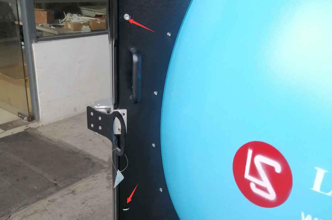
A1:We put two screws to lock the sphere during the transportation to avoid opening. Please just remove these two screws.

Q2:How to disassemble the big integrating sphere into two parts to facilitate transportation.
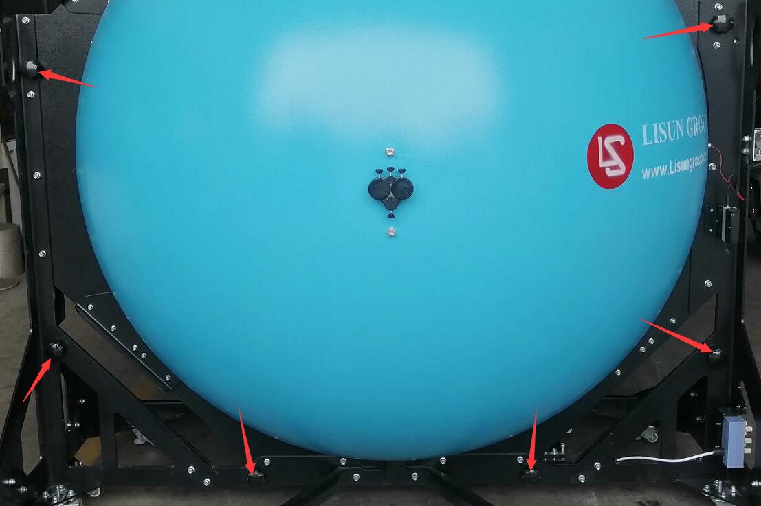
A2:First of all, it is not recommended to disassemble and transport it, as this will easily stain the internal coating. If you have to, please remove all the large black hand screws to disassemble the big integrating sphere into left and right parts. NOTE: Do not remove any other kind of screws. During transportation, please be careful not to dirty the internal coating of the integrating sphere.

Q3:The communication between software and hardware (LMS-7000 spectrometer, AC power source, DC power source, Power meter, etc) is failed.
A3:① There are two drivers. One is for the communication box and the other is for the LMS-7000 spectroradiometer. Please confirm that you installed both drivers successfully.

② Connect both USB cables to the black USB 2.0 ports of the computer.

③ Enter the “Device manager” of the computer (Please google it if you don’t know how to enter this interface). If you see the LMS-7000 device and four COM ports there, then the communication will be good.

Then please enter the “System configuration” interface, select the correct AC power source, DC power source and spectrometer model you purchased. Click “Search” and the correct port will be automatically found and a prompt will indicate successful communication.

Q4:When installing the LMS-7000 driver, it prompts that the installation failed.
A4:Driver files may be accidentally deleted by anti-virus software. Please temporarily close the computer anti-virus software and re-download the driver files. After the installation is successful, open the anti-virus software again.
Q5:The software prompts “The LMS-7000 communication disconnect” or “The spectrometer communication disconnect”.


A5: First, please confirm that the drivers are installed and the USB cables are all connected to the computer. Still unable to communicate, please follow the steps below to update the driver:
Enter “Device manager” of the computer (Please google it if you don’t know how to enter this interface). You can find the “LMS-7000” device here. Seeing exclamation marks, etc. on the device name indicates there is a problem with the communication.

Right click it and click “Uninstall device”.

Check “Delete the driver software for the device”, and click “Uninstall”.

Click “Scan for hardware changes”. The LMS-7000 is shown as “Unknown device”.

Download the latest driver here: https://lisungroup.myqnapcloud.com:5001/share.cgi?ssid=74916209c7054d99aa7ed67f9d4cc6f7
Double click “LMS-7000 Driver Setup” to install the driver.

Then you can find the LMS-7000 is ready to use.

Q6:A parameter on the front panel of digital power meter shows a negative value.
A6:Please check the wiring on the back of the power meter and confirm that the four wires A1 A2 V1 V2 are connected to the correct terminals.

Q7:The standard lamp can’t be turned on automatically.
A7:① Confirm that the AC/DC switch is at DC.

② Check “Auto power on” on the calibration interface. Input the correct voltage and current according to the calibration certification.

③ Confirm that the filament of the standard lamp is still good.

Q8:The installation direction of the sample.
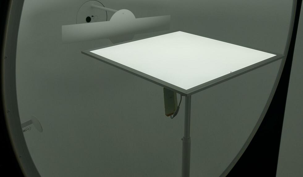
A8:The integrating sphere holder base can be installed on the top or bottom of the integrating sphere. When installed at the bottom of the integrating sphere, all lamps should be installed with the emitting direction facing directly upward, as shown below:
 On the contrary, if the holder base is installed on the top of the integrating sphere, all lamps should be installed with the emitting direction facing directly downwards.
Q9:Test results are not correct.
A9:① Confirm that the standard lamp is still in valid time (Its valid time is only 1 year). Recalibrate the system. After calibration, confirm that the CCT and flux values displayed at position 1 are close to the values that on the certification (CCT within 2k, and flux within 2 lumen).

Note: If the system is used frequently, it needs to be calibrated once a week. If the system is not used for a long time, it can be calibrated before next use. If too long has passed since the last calibration, the test data will be inaccurate.
② Confirm that you are using the correct assistant lamp revision coefficient. Bared light sources and small luminaires donot need to use assistant lamp revision coefficient. That is to say, the coefficient is 1. But big luminaires need to use assistant lamp to generate this coefficient (Please refer to the user manual for the detailed steps), and the coefficient is bigger than 1.

③ Please always check “Auto” for the “integration time” when you calibrate the system and run a test.
Calibration interface:

Measurement interface:

④ When using a big integrating sphere to measure small lights, the signal may be too weak; When using a small integrating sphere to measure big lights, the signal may be too strong. This may also lead to inaccurate test results. Please choose an integrating sphere of appropriate size for testing according to the actual situation.
⑤ Note: When you test big luminaires or directional luminaires, you need to use assistant lamp. Then the test results will be closer to the actual values, but there will still be errors. Such luminaires can be tested in a darkroom using a goniophotometer to obtain more accurate photometric parameters.
⑥ If the integrating sphere is used for too long, or care is not taken to protect the internal coating of the integrating sphere, resulting in serious damage to the internal coating of the integrating sphere, or a darker color, it will also lead to inaccurate test data.
Q10:During calibration or testing, the software prompts that the signal is too weak.
A10:The LMS-7000 spectroradiometer receives the optical signal from the integrating sphere through optical fiber. When calibrating or testing, please confirm that the standard lamp or sample lamp is normally turned on, and the optical fiber is properly connected to the integrating sphere. Otherwise, the software will prompts that the signal is too weak.
In addition, the optical fiber should not be bent excessively, otherwise it may cause the fiber to break and cause optical signal transmission problems.

Q11:Software can’t get electrical parameters.
A11:Please confirm that you selected the correct power meter model (Some power meters are only for AC, so please select DC power supply as the DC power meter if your sample is DC lamp) and the correct COM port. Please also check “Auto get electric parameter”.

Q12:Test results are unstable.
A12:If the luminous flux test results decrease steadily, it is just because the sample is not stable yet. Please preheat the sample for enough time before testing again.
If when testing some samples, the luminous flux test results fluctuate up and down, and the error is big, it is likely that the sample flickers too much (that is, the product is unqualified). Please enter the software “System Settings” and check the following option to obtain more stable test results. If the test results are still unsatisfactory, it is recommended to improve the quality of the lamp product, or consult us to upgrade the spectroradiometer to one more suitable for flickering lamps.

Q13:How to export spectrum data with intervals of 1nm.
A13:At the bottom of the software, select the corresponding test record, right-click and click “Save spectrum data to txt file” to save the detailed spectrum data as a txt file.

Q14:DC samples can’t be turned on automatically.
A14:Please confirm that the voltage and current of the sample is within the limit of the DC power supply. For example, the limit voltage is 30V and the limit current is 5A for DC3005S DC power supply.
If the sample needs constant current (CC), you need to input its rated current and a high enough voltage.
If the sample needs constant voltage (CV), you need to input its rated voltage and a high enough current.

Q15:When calibrating or testing DC samples, DC3005S cannot output, and the OVP or OCP indicator flashes to alarm.
A15:Someone may have mistakenly set the OVP or OCP parameters of the DC3005S incorrectly. Please exit the DC3005S from the output state, then press OVP, set to 30.5 and save to exit. Press OCP, set to 5.05 and save and exit. Then re-output.
If your model is DC6005S, then need to set the OVP to 60.5, and set the OCP to 5.05.
And so on.

Q16:How to maintain an integrating sphere.
A16:① The internal coating of the integrating sphere is very important, so you must wear white gloves whenever you are working inside the integrating sphere to avoid staining the internal coating of the integrating sphere.
② When the integrating sphere is not in use, keep it closed to prevent dust from entering. If dust gets in, use a blower to blow it out. Please do not use any contact materials to clean the inside of the integrating sphere, otherwise the coating may be damaged.
③ If the sample, etc. falls, causing a small area of coating inside the integrating sphere to peel off, please contact us. We can send you a small amount of paint free of charge to repair the peeling parts.
Q17:If you have not purchased DC power supply from LISUN, you need to do ZERO manually before calibration.
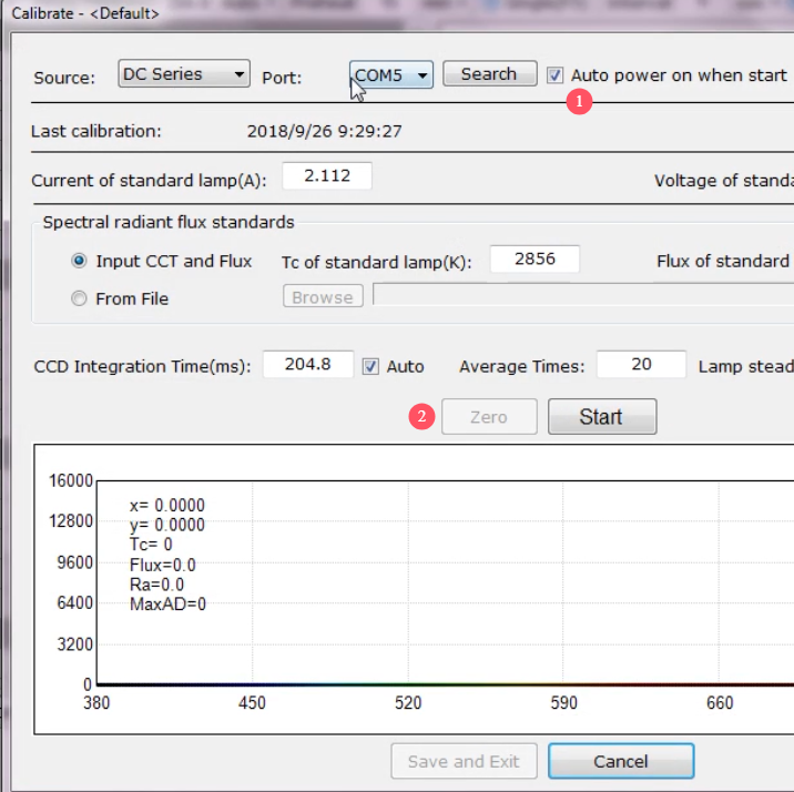
A17:If you have purchased LISUN’s DC power supply, you need to communicate with the DC power supply and check the “Auto power on” function when you calibrate as described in the user manual, as shown in the figure below. Then the ZERO button is not available, that is, the LMS-7000 will automatically ZERO before the calibration.
If you have not purchased LISUN‘s DC power supply, you do not need to check the “Auto power on” function, and the ZERO button will be available. Manually ZERO is required, otherwise it may affect the calibration and test data. The manual zeroing process is: make sure there is no light in the integrating sphere and it is closed and dark inside, and then click the ZERO button in the figure below. After the zeroing is successful, turn on the standard lamp for calibration.

Calibration and ZERO
Q18:If you have two LMS-7000 with different wavelength ranges, please pay special attention.
A18:Please use two computers to connect the two LMS-7000 respectively, and the original .lsd files cannot be mixed. If you use one computer to open the .lsd file of the other LMS-7000 connected with the other computer, the displayed data will be abnormal.
Q19:Can’t just double-click the .lsd file to view the test report?
A19:Although you can set the properties of the .lsd file to open it with the LMS-7000 software by default, you still cannot directly double-click to open the .lsd file. Thanks for your understanding. You need to open the LMS-7000 software first, and then open the corresponding .lsd file from the software, as shown in the figure below.

Open the LSD file with LMS-7000 software
Q20:Double-click the LMS-7000 software icon, but the sofware does not respond.
A20:Log in to the computer with an administrator account, as shown below:

Log in to the computer with an administrator account
Then right-click the LMS-7000 icon to view its properties. In the compatibility interface, check “Run this program as an administrator”, as shown below:

Run LMS-7000 software as an administrator
Then you can double-click to open the LMS-7000 software.
Lisun Instruments Limited was found by LISUN GROUP in 2003. LISUN quality system has been strictly certified by ISO9001:2015. As a CIE Membership, LISUN products are designed based on CIE, IEC and other international or national standards. All products passed CE certificate and authenticated by the third party lab.
Our main products are Goniophotometer, Integrating Sphere, Spectroradiometer, Surge Generator, ESD Simulator Guns, EMI Receiver, EMC Test Equipment, Electrical Safety Tester, Environmental Chamber, Temperature Chamber, Climate Chamber, Thermal Chamber, Salt Spray Test, Dust Test Chamber, Waterproof Test, RoHS Test (EDXRF), Glow Wire Test and Needle Flame Test.
Please feel free to contact us if you need any support.
Tech Dep: Service@Lisungroup.com, Cell/WhatsApp:+8615317907381
Sales Dep: Sales@Lisungroup.com, Cell/WhatsApp:+8618117273997
Your email address will not be published. Required fields are marked *