Electromagnetic Interference (EMI receiver) is electronic noise that interferes with cable signals and reduces signal integrity. EMI Receiver is usually generated by electromagnetic radiation sources such as motors and machines. EMI Receiver (Electromagnetic Interference) has two types: conducted interference and radiated interference. Conducted interference refers to the coupling (interference) of signals on one electrical network to another electrical network through a conductive medium. Radiated interference refers to the interference source coupling (interference) its signal to another electrical network through space.
When a product tested radiation launch in the laboratory, the radiation lack of radiation launch in the 1MHz-5MHz band was insufficient. The radiation launch of the 50MHz-100MHz band exceeded the standard 15dB. As shown in Figure 1, the experiments were not passed.


Figure 1 1MHz-100MHz radiation transcendence exceeding the standard
The whole machine is a metal shielding chassis with no holes on the chassis. The upper and lower shell gaps have conductive rubber strips. Check the exception spectrum. According to the relationship between the frequency and the wavelength, the wavelength corresponding to the 1MHz-5MHz and 50MHz-100MHz band is only comparable to the cable length, so it is suspected of the problem of the cable.
The system has three I/O cables for AC220V power cord, RS232 signal line, and radio frequency signal line. Among them, the radio frequency signal line is a shielding line, one end connects antenna, and one end is connected to the device. The end is well shielded. The AC220V power cord and the RS232 signal line are ordinary cables. Because the AC220V power supply is installed with a power filter, the 1MHz-5MHz electromagnetic interference generated by the switch frequency can exclude the power cord problem.
After the above analysis, suspected that the product radiation launch exceeding the standard is related to the RS232 signal line, remove the RS232 signal line, and the test spectrum is shown in Figure 2.

Figure 2 Unplug the RS232 cable 30MHz-100MHz radiation launch
As can be checked from the figure above, the electromagnetic interference of 50MHz-100MHz band after removing the RS232 cable disappears. Therefore, it is determined that the RS232 signal line that causes 50MHz-100MHz radiation is the RS232 signal.
Open the chassis and check the internal structure of the whole machine, as shown in the figure below.

Figure 3 Product internal structure and wiring
As can be seen from the figure above, the product AC220V power input, RS232 signal line, and power module DC output three cables are bundled together parallel wiring. Among them, the length of the RS232 internal jump line is about 300mm. Interference causes problems.
The operation of the switching power supply in the high -frequency switch is working, and it will produce strong electromagnetic interference during work, and the input and output cable of the switching power supply will become an important coupling path for electromagnetic interference. The input and output cables of the RS232 signal and switching power supply are tied together. At this time, the two will produce capacitive coupling, as shown in the figure below.

Figure 4 The principle of capacity coupling string disturbance
As can be seen from the figure above, the I/O interface RS232 signal line will coupling the interference on the output line of the power supply, which causes radiation in the RS232 signal line. The RS232 jump line and AC input and the jump line of the AC and DC output are separated from the space, as shown in the figure below.

Figure 5 Separate signal cable and power cord

Figure 6 RS232 signal line and power cord separate radiation emission
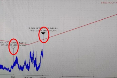
It can be seen from Figure 6 that although the frequency of 50MHz-100MHz interference decreases at this time, 50MHz and 200MHz narrow band interference at the same time are added. In the figure, there is a regular frequency point to determine the harmonic wave of the clock signal. Check the single board. There are 25MHz crystal on the main board. The adjusted RS232 signal line is just arranged on the crystal, which is caused by coupling, as shown in Figure 7.

Figure 7 RS232 signal line and 25MHz crystal vibration coupling principle
Based on the above analysis and verification, the RS232 signal line jumps longer, and the noise of the internal cables and devices in the system is easy to coupling the radiation launch problem.
The RS232 signal jumper isolates from the AC220V input and DC output, the power module interface, and the main board is isolated from the space, from the power module of the shielded shell to the I/O interface, as shown in Figure 8 and 9.

Figure 8 Search RS232 signal line and power supply diagram

Figure 9 isolation RS232 signal line and power physical map
After rectification by the above plan, test 10kHz-30MHz and 30MHz-200MHz frequency band radiation emission, as shown in Figure 10.

Figure 10 isolation RS232 signal line after radiation launch
It can be seen from Figure 10 that the frequency harmonics of the 1MHz-5MHz switch and the 50MHz-100MHz amplitude after rectification is reduced by more than 15DB, and the experiment passes.
Everyone says that EMC is a black box and a metaphysics, because it is difficult to determine what the mechanism of interference is. Many problems are inexplicable and incredible. Typical wiring such as cables, when you look at the mutual insulation between the two cables, there is nothing to do with each other when parallel wiring, and the world is peaceful. However, in fact, due to the coupling of the electromagnetic field between the line-lines, the inverse scale of the electromagnetic interference may be touched. If you are careless, you will lose. The radiation launch of the product in this case exceeds the standard. After meticulous diagnosis and analysis, it is caused by the inter-line-line capacity coupling, and then successfully resolved through different types of cable classification wiring of different types and properties.
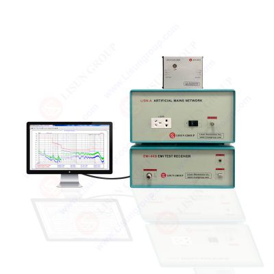
EMI receiver system for EMI (Electromagnetic Interference) radiation conduction or conducted emissions testing. The EMI-9KB EMI receiver is produced by the full closure structure and strong electro-conductibility material, which has high shielding effect. Due to the new technology for the EMI Test System, it solved the instrument self-EMI problem. The test results are according to the international format test report. The EMI Test System EMI-9KB fully meets CISPR15:2018, CISPR16-1, GB17743, FCC, EN55015 and EN55022.

EMI Receiver and EMI Testing Equipments
Lisun Instruments Limited was found by LISUN GROUP in 2003. LISUN quality system has been strictly certified by ISO9001:2015. As a CIE Membership, LISUN products are designed based on CIE, IEC and other international or national standards. All products passed CE certificate and authenticated by the third party lab.
Our main products are Goniophotometer, Integrating Sphere, Spectroradiometer, Surge Generator, ESD Simulator Guns, EMI Receiver, EMC Test Equipment, Electrical Safety Tester, Environmental Chamber, Temperature Chamber, Climate Chamber, Thermal Chamber, Salt Spray Test, Dust Test Chamber, Waterproof Test, RoHS Test (EDXRF), Glow Wire Test and Needle Flame Test.
Please feel free to contact us if you need any support.
Tech Dep: Service@Lisungroup.com, Cell/WhatsApp:+8615317907381
Sales Dep: Sales@Lisungroup.com, Cell/WhatsApp:+8618117273997
Your email address will not be published. Required fields are marked *