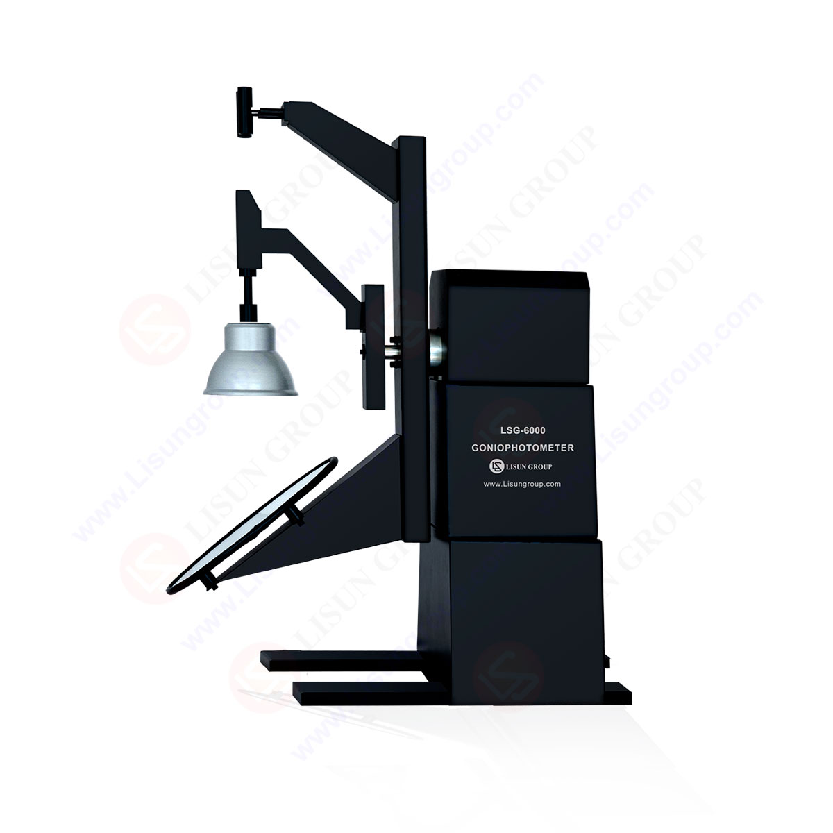
LM-79 Moving Detector Goniophotometer (Mirror Type C)
LSG-6000
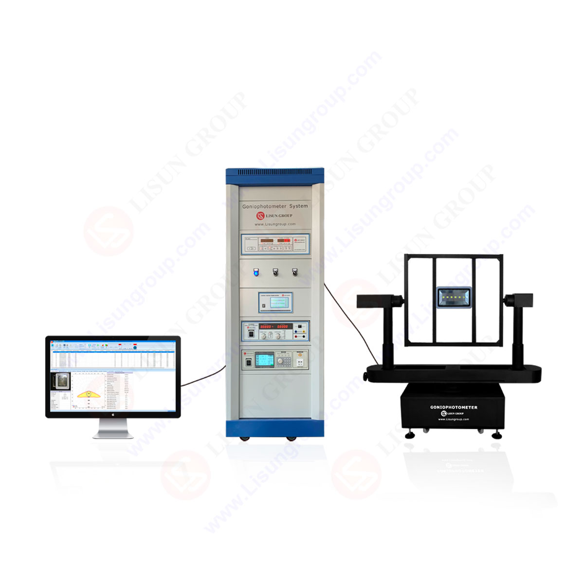
High Precision Rotation Luminaire Goniophotometer
LSG-1890B
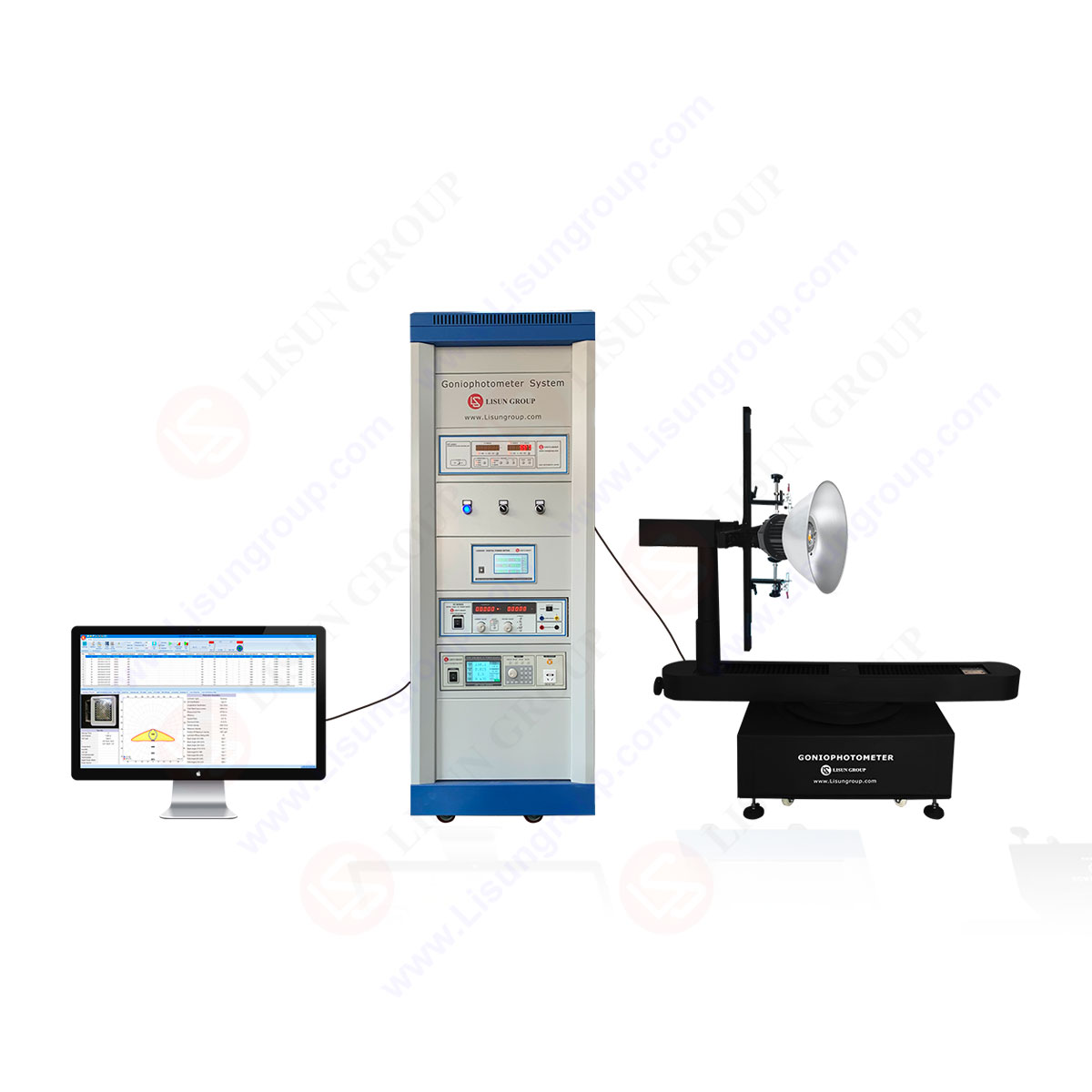
High Precision Rotation Luminaire Goniospectroradiometer
LSG-1890BCCD
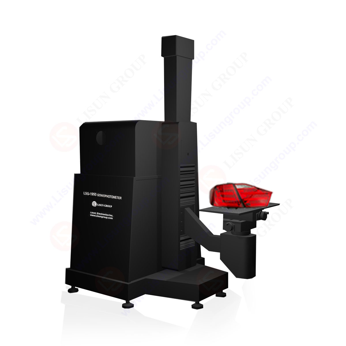
Goniophotometer for Automotive and Signal Lamps
LSG-1950
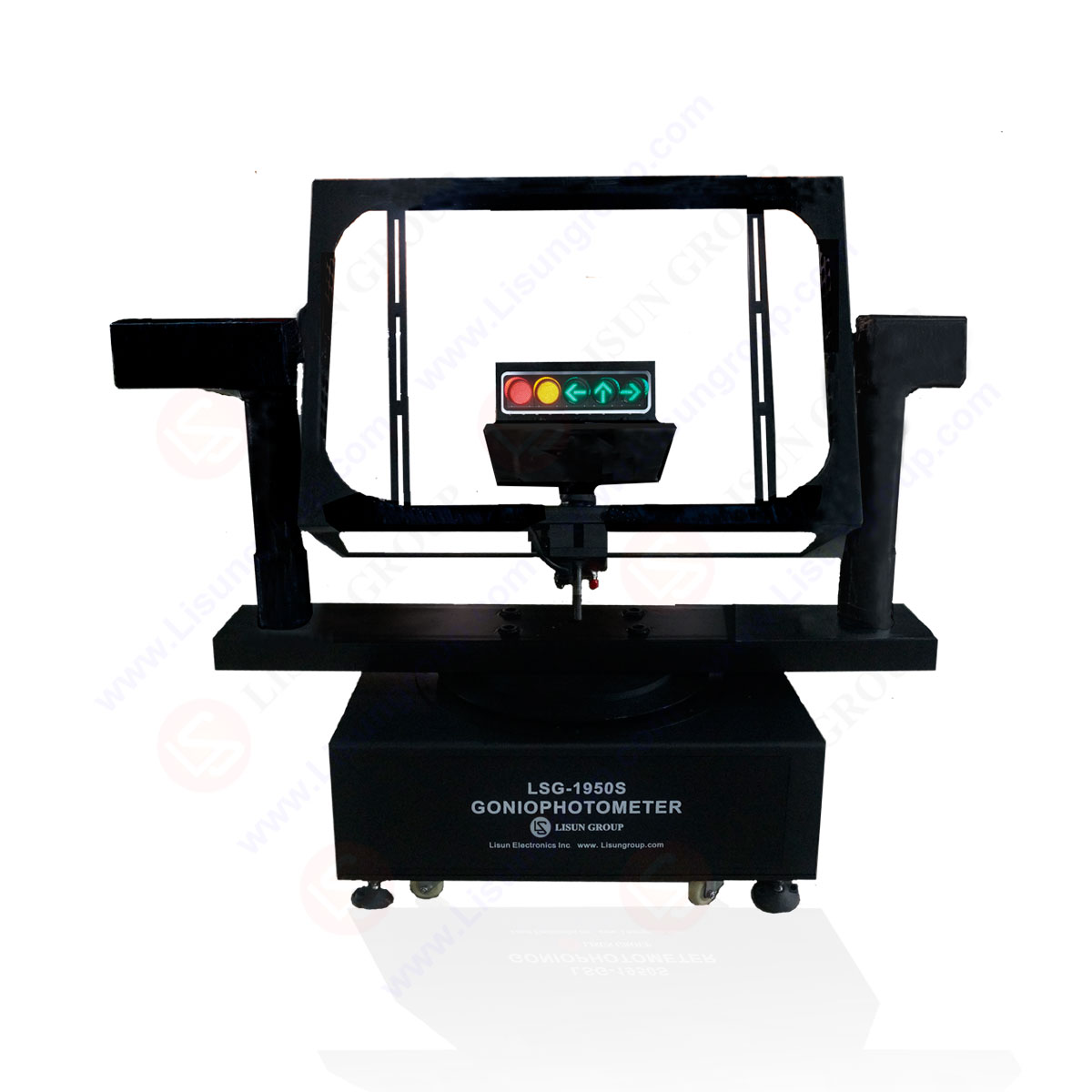
Goniophotometer for Traffic Signal Lamps
LSG-1950S
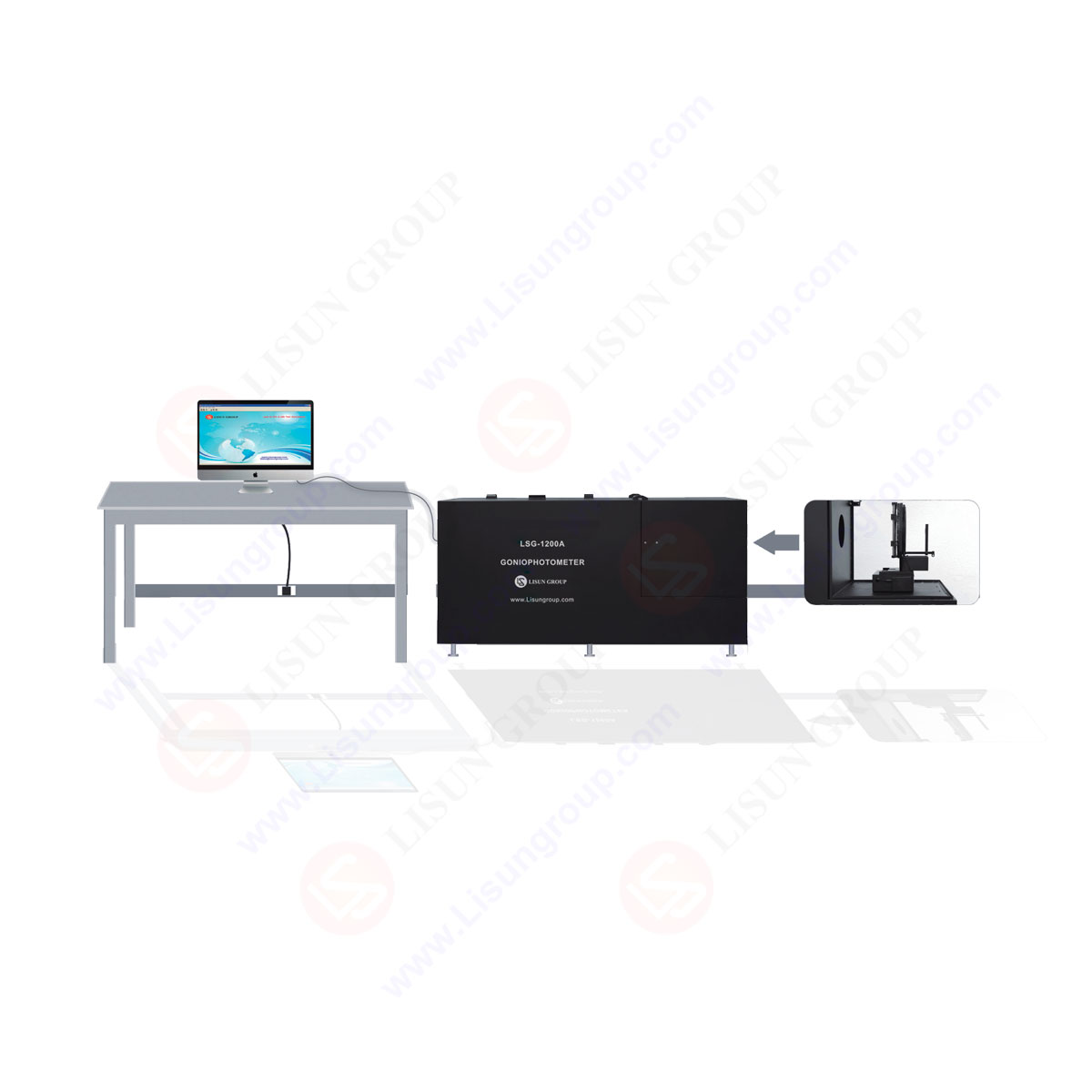
Compact Goniophotometer
LSG-1200A

Near Field Moving Detector Goniophotometer
LSG-1900B
 LEDs and Luminaire Test Solutions
 LM-79 and LM-80 Test Solutions
 LED Driver Test Solutions
 Household Appliances Test Solutions
 Mobile and Network Test Solutions
 Automotive Electronics Test Solutions
 Audio-Video and IT Test Solutions
 Cable and Wire Test Solutions
 Plugs and Sockets Test Solutions
 Power Switch Test Solutions
 Transformer Test Solutions
 Electric Toys Test Solutions
 Energy Meter Test Solutions
 Motor-Operated Tool Test Solutions
Select an organization
to browse standards
Probe Test
A tamper-resistant receptacle shall not permit contact to be made between the probe test shown in Figure 132.1 and Figure 132.2 and any live part of the receptacle through the outlet slots when tested as described in this section.
Twelve previously untested devices are to be used for this test. The probe test shown in Figure 132.1 is to be applied to each of the outlet slot openings of the receptacle with a force of 8 ounces (2.2N) in an attempt to bypass the tamper-resistance mechanism. A suitable indicating device (such as an ohmmeter, battery-and-buzzer combination, or the like) is to be connected between the probe and the wiring terminal of the outlet slot being tested to determine whether contact is made.
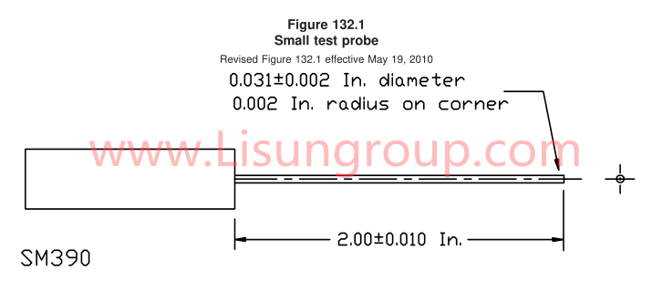
Small Probe Test of UL498 Figure 132.1
The probe test is to be manipulated in the outlet slots in any orientation that may permit access to live parts within the receptacle.
Twelve devices previously tested in 132.2 are to be used for this test. The probe test shown in Figure 132.2 is to be applied to each of the outlet slot openings of the receptacle with a force of 10 pounds (45N) in an attempt to bypass the tamper-resistance mechanism. A suitable indicating device (such as an ohmmeter, battery-and-buzzer combination, or the like) is to be connected between the probe and the wiring terminal of the outlet slot being tested to determine whether contact is made.
The probe test is to be inserted in the outlet slots successively in three directions in any orientation that may permit access to live parts within the receptacle. The probe is applied for approximately 5 seconds in each of the three directions. During each application the gauge shall not be moved or rotated and shall be withdrawn when moving from one direction to the next.
Tags:GNGPL-SM390Your email address will not be published. Required fields are marked *

 English
 中文简体
中文简体 English
 Русский
 Español
 Português
 Türkçe
 العربية
 Deutsch
 Polski
 Italiano
 Français
 한국어
한국어 ไทย
ไทย Tiếng Việt
 日本語
日本語